


SpeedyBee F7 V3 flight control BL32 50A electric control 30x30 flytower F722 V3 single flight control APP adjustment
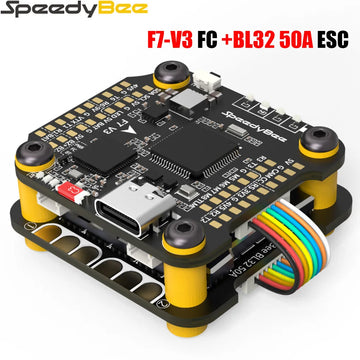
SpeedyBee F7 V3 flight control BL32 50A electric control 30x30 flytower F722 V3 single flight control APP adjustment
Name:SpeedyBee F7 V3 Flight Controller
MCU:STM32F722
IMU(Gyro):SBMI270
USB Port Type:SType-C
Barometer:SBMP280
OSD Chip:SAT7456E chip
BLE Bluetooth:Supported. Used for Flight Controller configuration
Flash FC Firmware Wirelessly:SSupported. Please enter MENU > FC Firmware Flasher
Download/Analyze Blackbox:Supported.Please enter MENU > Blackbox Analyzer
DJI Air Unit Connection Way:Two ways supported: 6-pin connector or direct soldering.
Flash(for BlackBox):500MB
BetaFlight Camera Control Pad:Yes(CC pad on the front side)
Power Input:3S - 6S Lipo
5V Output:
10 groups of 5V output, three +5V pads and 1 BZ+ pad( used for Buzzer) on front side, and 6 +5V output included in the connectors on bottom side. The total current load is 2A.
9V Output:
2 groups of 9V output, one +9V pad on front side and other included in a connector on bottom side. The total current load is 4A.
3.3V Output:
Supported. Designed for 3.3V-input receivers. Up to 500mA current load.
4.5V Output:
Supported. Designed for receiver and GPS module even when the FC is powered through the USB port. Up to 1A current load.
ESC Signal Pads:
M1 - M4 on bottom side and M5-M8 on front side.
UART:
5 sets(UART1, UART2, UART3, UART4(For ESC Telemetry), UART6)
ESC Telemetry UART:R4(UART4)
I2C:Supported. SDA & SCL pads on front side. Used for magnetometer, sonar, etc.
LED Pad:Used for WS2812 LED controlled by Betaflight firmware.
Buzzer:BZ+ and BZ- pad used for 5V Buzzer
BOOT Button:Supported.
[A]. Press and hold BOOT button and power the FC on at the same time will force the FC to enter DFU mode, this is for firmware flashing when the FC gets bricked.
[B]. When the FC is powered on and in standby mode, the BOOT button can be used to controller the LED strips connected to LED1-LED4 connectors on the bottom side. By default, short-press the BOOT button to cycle the LED displaying mode. Long-press the BOOT button to switch between SpeedyBee-LED mode and BF-LED mode. Under BF-LED mode, all the LED1-LED4 strips will be controlled by Betaflight firmware.
RSSI Input:Supported. Named as RS on the front side.
SmartPort:Use any TX pad of UART for the SmartPort feature.
Supported Flight Controller Firmware:BetaFlight(Default), EMUFlight, INAV
Firmware Target Name:SPEEDYBEEF7V3
Mounting 30.5 x 30.5mm( 4mm hole diameter)
Dimension:41(L) x 38(W) x 8.1(H)mm
Weight:10.7g
SpeedyBee BL32 50A 4-in-1 ESC
Firmware:SpeedyBee BL32 50A
Configurator Download Link:http://github.com/bitdump/BLHeli/releases
Continuous Current :50A * 4
Burst Current:55A(5S)
TVS Protective diode:Yes
Heat Sink:Yes
External Capacitor:1500uF Low ESR Capacitor(In the package)
ESC Protocol:DSHOT300/600
Power Input:3-6S LiPo
Power Output:VBAT
Current Sensor:Support (Scale=490 Offset=0)
Mounting:30.5 x 30.5mm( 4mm hole diameter)
Dimension:45.6(L) * 40(W) * 8.8mm(H)
Weight:19.2g with heat sink
Shipping cost is based on weight. Just add products to your cart and use the Shipping Calculator to see the shipping price.
We want you to be 100% satisfied with your purchase. Items can be returned or exchanged within 30 days of delivery.